


The fabrication and installation of the China Pavilion was a monumental effort that was accomplished in a very short timeframe of six months. A joint team including the client, Tsinghua University, architects, engineers, and builders from three continents worked intensely and effectively for many months, collaborating on a daily basis to ensure that the pavilion was ready for visitors when Expo Milano opened on May 1, 2015.
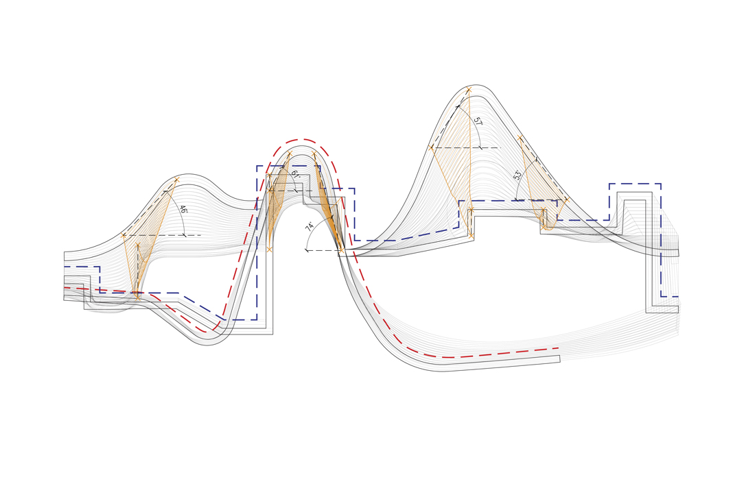
Rafter overlay diagram showing the transition between the city skyline (blue) and the rolling landscape (red).
The roof of the China Pavilion was designed as an exposed glulam structure. Inspired by Chinese traditional “raised beam” construction, the design utilized contemporary engineering to create the long spans required by building’s public program. Through rigorous calculation, a roof structure with spans of up to thirty-seven meters and slim vertical columns was created. Designed to float over the site, the timber roof is physically separated from the exhibition area beneath. This created the sense of openness mandated by the design concept and echoed Asian architectural tradition, in which walls stop short of the roof, allowing interior spaces to flow horizontally and merge into each other.
The structure was designed to reinforce the reading of the “landscape to city” gesture. The form created by the initial merging action was articulated via a series of east-west rafters that created cross sections through the roof form, spaced two meters apart. Each rafter captured a specific moment within the transition, allowing viewers to read the concept clearly from within the pavilion. In addition, the rafters created a sense of frozen motion within the space, an effect similar to what was famously captured in stop-motion photographs taken by Étienne-Jules Marey or Harold Edgerton in the late nineteenth and early twentieth centuries.
The east-west rafters were the deepest structural elements in the roof assembly. The north-south purlins required to create a structural roof grid were kept shallower than the rafters, emphasizing the design gesture and bringing clarity to the space beneath.
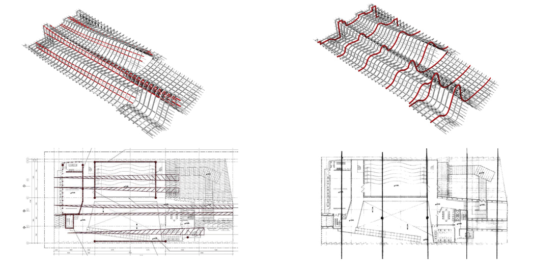
Early diagrams for the China Pavilion roof structure. The images to the right show major roof rafters, and the diagram and images to the left show north/south cable trusses embedded in the roof ridges.
Engineering this roof structure required intense collaboration and expertise. Link-Arc worked closely with the New York office of Simpson Gumpertz & Heger (SGH) and F&M Ingegneria, the Italian architect and engineer of record, to successfully realize the roof structure.
During the early stages of the design process, the architect expressed a desire to create a light roof structure—ideally, the rafters would be 40 centimeters deep. This shallow structural depth, combined with the pavilion’s complex form, meant that the roof structure needed to be heavily reinforced. This was accomplished using three primary methods. The first method was to reinforce the glulam rafters. Structural steel elements would be inserted into the wood and set with epoxy so the timber and steel could act together to create a rigid roof structure. Rafters and purlins that were designated as major structural elements would require more substantial internal reinforcement, while less critical structural elements could have less reinforcement or none at all. The second reinforcement strategy was to create a network of steel cable trusses embedded in the roof form. These trusses would be located in more vertical areas of the roof to improve their structural efficiency and increase structural spans, completely eliminating the need for columns within the main installation space. And finally, each intersection in the roof was designed as a moment connection so the roof would move as a single element (a diaphragm) that would efficiently transfer the lateral forces on the structure to the building’s vertical columns and shear walls.
During later stages of the design process, however, it became evident that realizing this structural design proposal in its entirety would be difficult. Embedding steel reinforcement inside the timber rafters would create a large amount of extra fabrication effort. In addition, the shallow structural depth mandated the use of a high-strength grade of wood and it would be difficult to obtain this material in time. Given the project’s tight budget and compressed schedule, a number of changes were proposed to simplify fabrication and construction. The first modification was to create a network of exposed steel rafters and purlins (the “major” structural elements in the previous scheme). The second change was to increase the depth of the roof structure. The east-west rafters became 56 centimeters deep.
These modifications offered a number of benefits. The steel structure could be erected first and would support the timber rafters as they arrived on site and were bolted into place. This minimized the need for temporary scaffolding on site and allowed construction to occur simultaneously beneath the roof. The new steel rafters and purlins stiffened the roof structure greatly, eliminating the need for moment connections in the timber roof structure. This meant that the typical rafter-purlin details could be simplified. Finally, increasing the structural depth meant that a standard grade of glulam timber could be used and internal steel reinforcement was not required. This would greatly expedite the manufacturing of the rafters.
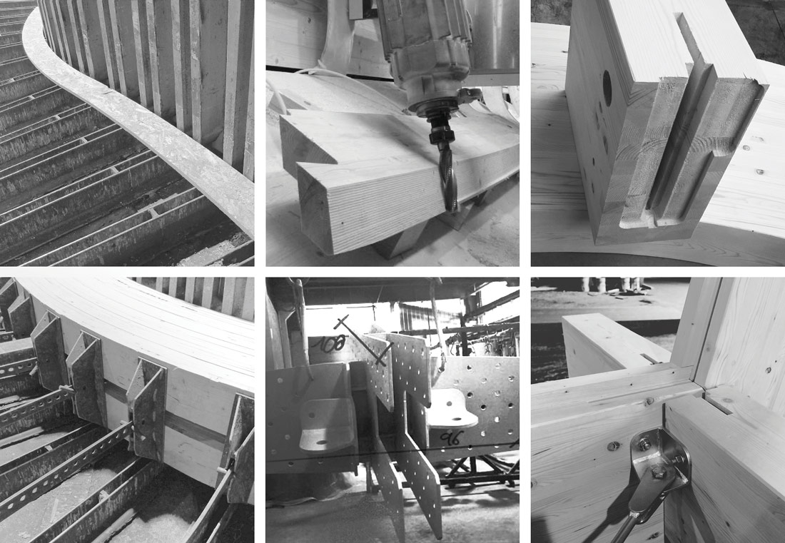
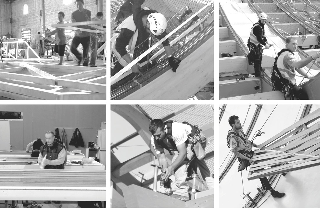
The fabrication of the roof structure (clockwise from upper left): steel angle molds ready to receive glulam; CAD/CAM fabrication; milled joint pockets; structural mockup; steel bracket plates in production; and clamped timber layers drying in the molds.
Once the engineering was finalized, the fabrication process began in earnest. Given the complexity of the roof and the tight construction schedule, a typical shop drawing review and approval process made very little sense. Instead, the final review and approval of the fabrication scheme was handled via electronic collaboration between Italy, New York, and China. Stratex SpA, the selected Italian timber fabricator, built a CAD/CAM model based upon Link-Arc’s master digital model. Stratex started the process by sending digital 3D models of the most typical roof connections for Link-Arc to evaluate within its own model, streamlining the review process greatly. Once the basic detail typologies were approved, the final engineering moved quickly.
However, even with the newly simplified structural scheme, producing the timber roof was an enormous task. The pavilion’s complex roof geometry meant that each individual rafter-purlin connection (there were over 1400) was different and had to be modeled individually. The typical rafter-purlin connection consisted of two steel bracket plates attached to a continuous rafter. Each bracket would receive a purlin with a corresponding pocket carved from the end. This meant that to finalize the roof, 1400 unique bracket plates and 1400 joint pockets, along with thirty-one timber rafters and 700 purlin sections, had to be designed, modeled, and produced within the span of a few months.
To accomplish this, the timber fabricator and the general contractor collaborated extensively, using a combination of digital and manual production techniques. The rafter sections were first formed via a very manual process. Timber strips were glued and clamped in steel angle molds that had been manually welded to the factory floor to match the rafter elevations. Once dry, these rafter sections were removed from the mold and finished to final tolerances, using CAD/CAM equipment. Since the majority of the purlins were straight, creating the raw sections was very straightforward. As with the rafters, the purlin sections were finished to final tolerances and the joint pockets were cut via CAD/CAM.
While the rafters and purlins were being produced, the general contractor took responsibility for manufacturing the steel brackets within each roof joint. Using the CAD/CAM model produced by the timber fabricator, the contractor produced two-dimensional shop drawings for each bracket plate, which were then distributed to a network of steel fabrication shops in Torino for cutting, drilling and welding. Some of these steel bracket plates weighed in excess of 500 pounds after assembly.
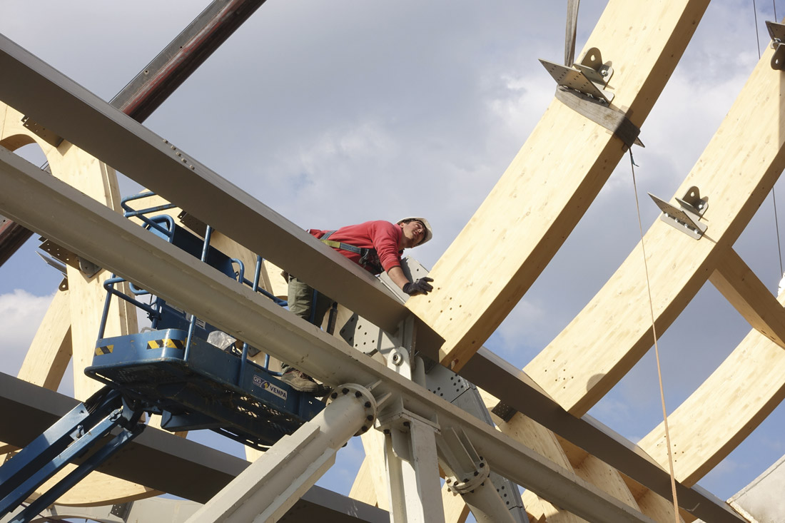
Timber structure being erected on site. The steel structure, installed earlier, functions as a scaffolding for the timber.
The timber structure began fabrication in northern Italy in December of 2014. The last timber rafter was installed on site in the middle of March 2015.
While the design team was finalizing the roof structure, there was also the question of how to deal with the waterproofing layer, which proved to be one of the most complex and interesting technical components of the project. Sandwiched between the timber structure, the roof panels, and the supporters, this translucent roof membrane would have to deal with many technical issues unique to the project. It had to be watertight and handle drainage effectively, needed to allow natural light to filter into the space beneath, and had to work with the complex roof form without requiring excessive customization.
The team had initially explored two material options for the waterproofing layer: translucent polycarbonate and PVC membrane. Link-Arc initially hoped to use polycarbonate, as the material would create a rich visual effect when seen from below—a roof mockup produced in Italy had proven this very clearly. However, using polycarbonate as a roofing material would be difficult for a number of reasons. The material came in finite sizes and was not particularly pliable. As a result, many individual pieces of polycarbonate would be needed to create the waterproofing layer. This would create many joints that would need to be supported and sealed individually on site. The panels would also have to be formed or slumped to match the roof surface, which would add complexity, expense, and time.
A collage of construction photos (clockwise from upper left): aluminum panel frames fabricated in China; installation of waterproofing extrusions; PVC installation; bamboo panels being installed; supporters being installed; and panel assembly.
While a number of parties had suggested the usage of PVC membrane for the waterproofing layer, this was initially not viewed positively as many of the available material choices were either too opaque or too transparent to create the effect the design team desired. Eventually, a relatively new translucent PVC product from Japan was proposed and reviewed in a separate mockup. While the light effect was different from that created by the polycarbonate panels, the shadows cast by the bamboo panels on the PVC membrane were still quite striking. Most importantly, the PVC option offered a number of advantages: since pieces of the material could be heat-welded together with special equipment, the entire waterproofing layer between two rafters could be a single continuous piece of membrane from east to west with only a few seams. The seams could be located above the purlins and would be completely invisible from beneath. To fix the membrane to the structure, the fabricator devised a continuous aluminum extrusion that attached to the top of the rafter. This extrusion accommodated the tensioners that would keep the membrane tight and waterproof and incorporated a continuous track that would hold the panel supporters without penetrating the extrusion, maintaining the watertightness of the system.
The roof membrane was produced by a specialized fabricator located south of Milan. The PVC arrived on site in thirty-four continuous bands (matching the unfolded roof geometry), and were installed from north to the south in twenty days.
The final component of the roof construction was the assembly and installation of the bamboo roof panels and supporters. The information produced by Link-Arc (the panel shop drawings and the detailed digital models of both the supporters and the panels) were central to this process.
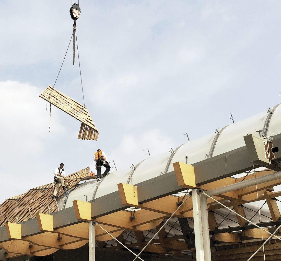
Bamboo panels being installed on the China Pavilion roof.
The bamboo strips and the aluminum frames for the China Pavilion’s roof panels were fabricated in China from Link-Arc’s shop drawings and shipped to Torino for assembly. The contractor used Excel to extract geometric information and component quantities from the master digital model to produce the supporters.
While the panels and supporters were being assembled, Link-Arc and the general contractor created a set of drawings to guide the panel installation. A separate sheet detailing the fixing procedure for every single panel was produced, ultimately numbering over a thousand. The drawings showed the installers how each panel was oriented relative to the roof structure, how it attached to the roof supporters, and where panel-to-panel connections had to be made. These drawings proved invaluable to the process, as the roof panels were installed very quickly.
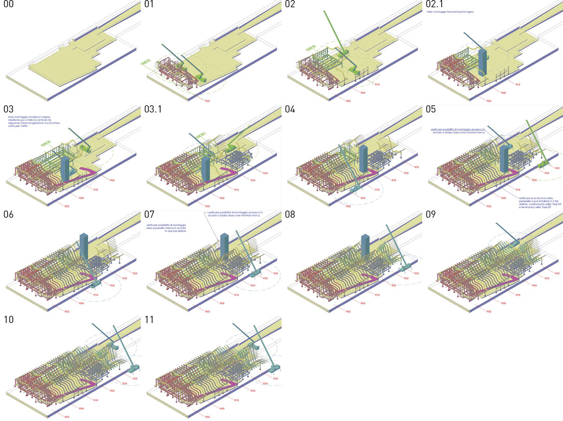
A construction phasing drawing detailing the installation sequence for the pavilion roof structure.
At the peak of the installation process, the local construction team placed over fifty panels per day. The installers worked in two directions, placing panels from the north and from the south. The rapid-fire process required a highly coordinated logistical effort. Link-Arc and the contractor located an architect and engineer on site, both dedicated solely to ensuring that the correct panel was at the pickup location at the right time. With over a thousand panels and a very constricted construction site with very little room to work, this was a complicated effort. At the peak of construction, one panel was hoisted to the roof by a crane every twenty minutes. Once the panel was on the roof, two installers captured the panel, maneuvered it into place, and secured it to the supporters using the panel installation drawings as a guide. All of the panels—one thousand and fifty-two pieces —were installed in thirty days.